43. Poynting's Theorem for Harmonic Fields: Impedance and Admittance
Jackson section 6.9
Introduction
The point of this exercise is to use Poynting’s theorem to track energy flow in a two-terminal electrical device: AC energy is supplied through the terminals. We assume that all charge densities, currents and fields are oscillating at frequency Obviously, this scenario is extremely common in the real world, from AC to GHz and beyond. Some of the energy will be transformed to heat in the resistance, some will be stored cyclically in the capacitance and/or inductance, some will be radiated away.
Harmonic Maxwell’s Equations
As usual, we write fields and currents as complex numbers, with the understanding that the physical quantity is just the real part,
Note that the amplitude function is itself in general complex: the oscillating field can have different phases at different places.
The local rate of working of the fields on the currents is
Maxwell’s equations for harmonic fields are
with all fields complex.
The real part of
is the time-averaged rate of work done by the fields in the volume (Another way to see that the half comes from the time averaging: suppose locally the field goes as the current density as Then the product goes as averaging to over a cycle.)
From Maxwell’s equations,
(Using )
Defining the complex Poynting vector (again, the factor because these are harmonic fields)
and the harmonic electric and magnetic energy densities
we have
The real part of this equation gives the time-averaged quantities, the imaginary part is the reactive or stored energyas the current oscillates in an inductance, for example, energy is constantly exchanged between the driving voltage source and the magnetic field. The effect is to change the relative phase of electric field and current.
If the conductors are perfect, and the dielectrics lossless, the energy density volumes in the middle term are real, meaning the term itself is pure imaginary, so the real part of the equation is:
the time-averaged rate of working by the electric field on the charges in the volume equals the averaged flow of power (integrating the Poynting vector) into the volume.
Compare with the following simple example: find the heat dissipation from a steady DC current in a straight uniform piece of wire, one meter long and total resistance Do this by finding the magnitude and direction of the Poynting vector at the surface of the wire. What is the total rate of inflowing energy from the field? (Of course, it must be )
Now consider a loop of wire from one terminal of a battery to the other. A steady current flows. Sketch the energy flow from the battery into the wire through space.
Finally, sketch the fields and Poynting vector for current in a coaxial cable. How would that change if you allow for some resistance in the conducting material?
Two-Terminal Passive System
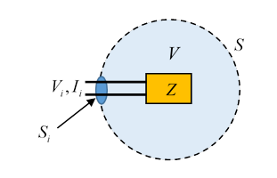
We'll now consider a two-terminal passive system (meaning no internal energy source). The power is supplied through two input leads, voltage and current so the time-averaged power input is . We take it (with Jackson) that this power is all being delivered through the small input surface , so we can write input power (the normal points outwards as usual, hence the sign). The way to deliver the power through such a small area is to have the external source a coaxial cable.
Jackson writes:
This is interpreted as the ingoing power going to ohmic losses, energy exchange with electric and magnetic field energies in system capacitance and inductance, and outward flow through As Jackson states, if we can balloon to infinity, only the radiation power survives in the Poynting integral (the other fields decay more rapidly with distance).
We can write the impedance
with the resistance and the reactance, defined by (input voltage and current), so
(This is assuming the power flow outwards is real.)
Notice the reactance is positive if magnetic energy dominates, that is, inductance. (To keep you on your toes, Jackson has switched from to and the imaginary part of is given a negative sign.)
Recall that for simple low-frequency AC circuits, the impedance has negative imaginary part (reactance) for inductance, for capacitance.
At low frequencies, the “radiation resistance” is small and ohmic heating dominates.
Wait, what about admittance?
It appears in the heading of this section in Jackson, but not in the text until the very last word, which refers the reader to one of the end-of-chapter problems. It’s the inverse of impedance, handy in AC circuit theory for analyzing shunts for transformers, but not, I think, central to our task here. I note that the inverse of resistance (measured in ohms, of course) is now officially measured not in mhos, as was suggested by Lord Kelvin and used for at least a century, but in siemens. Not a great improvement, I MHO.