45 Impedance 101
What’s the Point of This Lecture?
One unfortunate aspect of Jackson’s book is that he barely mentions, and does not really use, the concept of wave impedance. Yet as is made clear in Zangwill’s book, and in the excellent online notes of Likharev, the most natural parameters for describing waves (of any kind) going from one medium to another are the wave velocities and the wave impedances for the two media. In the next few lectures, we’ll be discussing electromagnetic waves: in vacuum, in media and in various pipes (waveguides, resonators, etc.). In particular, we’ll be analyzing wave transmission from one medium to another. We’ll use impedance a lot, so, since it’s not featured prominently in many introductory physics texts, we’ll introduce it here with a simple example.
Waves on a String
The simplest system with the essential ingredients is, I think, small amplitude waves on a taut uniform string: tension linear density We need to find out what happens when this string is joined to another one having different density, or possibly tension, and a wave is sent towards the join.
We’ll review the relevant sections of Waves, Berkeley Physics Course, Volume 3, by Frank Crawford.
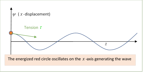
Following Crawford, the string is taken to be along the axis (yes, not the -axis!) from the origin to a large positive distance, and is harmonically driven at the origin by a “transmitter”, oscillating harmonically in the direction. The wave amplitude is (using Crawford’s notation)
from which and
(Note: Crawford distinguishes between the string tension and its equilibrium tension We won’t: we’ll consider only small amplitude waves, and that difference is third order in the angle of slope.)
A natural question is: what transmitter power is necessary to produce a wave train of a given amplitude traveling down the string?
We assume the relationship for waves on the string is linear, being the phase velocity (if you’re rusty on where this comes from, look at my notes here) so
To find how hard the transmitter has to work to generate a given wave the (vertical) force the string exerts on the transmitter (see diagram) is
This is the resistance force the string presents to being made to wave at this velocity, and the multiplying constant is called the impedance (or sometimes the amplitude impedance) and written
That is,
and using the impedance
Exercise: Check the dimensions are the same as those of force/velocity.
Using to express the power (rate of working of transmitter, force component times velocity) generating the traveling wave, with
Since there is no friction in the system, this power is traveling with the wave and, given the right receptor, it can be fully recovered at any later point along the -axis.
But what happens if the wave encounters a different medium?
Transmission and Reflection
To be specific, we assume that at the string is joined to one of a different density, but they are pulled tight so the tension is the same throughout.
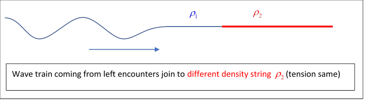
We know from experience that in general the wave is partially transmitted, and partially reflected. We can find the relevant amplitudes from the requirements that the wave amplitude and its slope must be the same for both strings at the join: the forces must balance there, or the infinitesimal bit of string at the join would have infinite acceleration (the tension is the same throughout).
Consider the situation after the (semi-infinite) wave train front has passed the join: there is still incoming wave
on the left, generating a force on the join:
This is balanced to some extent by the force from the string on the right. But if since is the same for both, the forces can’t balance: the change in impedance means that simple transmission doesn’t work, it’s termed an impedance mismatch.
The solution (as you know) is that some of the wave is reflected, and the amount reflected is given by balancing out the impedance mismatch. The transmitted and reflected waves have necessarily the same as the initial wave (all must match at ), the reflected wave is in the same medium as the incoming wave, so has the same wave number but is going backwards, take its amplitude to be :
The transmitted wave will have a different wavenumber, since so, in the obvious notation,
(This is why I’m not using for string tension here, although it’s standard.)
Matching amplitudes and slopes of and at
From this, writing the first equation as then adding and subtracting,
Exercise: Open the animation, and notice how the reflected wave is different depending on which string is denser.
Impedance Equations
Furthermore, from we have so we can write the reflection and transmission amplitudes in terms of the impedances:
Important: this makes clear that for this linear system, the transmission coefficient depends only on material properties not on the wavelength of the wave.
If the impedances match, there is no reflection, the wave goes on. For the wave changes sign on reflection. For the transmitted amplitude is larger than the incoming wave (watch the animation), but of course having less energy.
Different String Tensions
A more interesting situation rises if we allow the two strings to have different tensions. This could be accomplished by taking the join to be a very small ring, moving frictionlessly up and down a fixed rod parallel to the -axis. The requirement now is that the -direction forces on the ring must balance,
at so
This time (since )
so
and the above impedance equations for transmission and reflection are still correct.
It’s worth noting that if the strings have different densities, but also different tensions in the opposite ratio, there will be no reflection: the wave train will go through, with altered speed and wavelength but the same power transmission rate. We say the impedances are “matched”, clearly desirable for signal transmission through a join in cables.
These same impedance equations appear in many branches of physics, for example light transmission normal to a surface, discussed below.
Impedance in AC Circuits
Jackson spends no time on conventional AC circuit theory, assuming (I hope reasonably) that you’re fully familiar with it from undergraduate studies. If you want to brush up, you can’t do better than to read Feynman’s lecture on the subject: vintage Feynman, entertaining and with some very cute examples.
The reason I bring AC theory up here is that it affords further insight into the nature of impedance. AC impedance is the generalization of simple resistance in DC circuit theory. Kirchhoff’s laws are still good for analyzing a general circuit, but now the alternating current in a leg (meaning a component of a circuit with one current in it, but it could include resistance, inductance, capacitance) is generally out of phase with the alternating applied voltage, so both driving force and response are most naturally represented by rotating complex numbers, the engineers call them phasors. The impedance of a single leg of a circuit can be written as where is the ordinary resistance, and is termed reactance, generated by inductance and/or capacitance elements, for which current and voltage are ninety degrees out of phase, hence they contribute terms and
That is to say, for an AC circuit Ohm’s (DC) Law with all numbers real of course, goes to
where is a (non-time varying) complex impedance, and are complex numbers rotating at the same rate in the complex plane, with phase difference equal to the phase of the impedance.
If we have a generator which is part of a circuit having inductance and capacitance, driving a load which itself has resistance, inductance and capacitance, the power transfer is at a peak when the impedances are matched: to be precise, the load circuit impedance must be the complex conjugate of the generator circuit impedance. Detailed proof available here.
Impedance in the Reflection of Light
We’ll discuss reflection of light fully in the next lecture, but we’ll find that for normal incidence of light from one medium to another, the transmission and reflection coefficients are almost the same as those for the string example above:
where now the impedance is given in terms of the permittivity and permeability:
It is instructive to note (Zangwill p 592) that if we assume uniform magnetic properties, and then rewrite these equations in terms of the refractive indexes, we find
precisely the same as the equations for the string impedances discussed earlier, so evidently the refractive index is analogous to the string impedance as we defined it: the denser string corresponds to the denser medium.
But so the electromagnetic parameter that apparently corresponds to the string impedance is the inverse of the usually defined electromagnetic wave impedance ! How can they both make sense?
To go back to the string: if the string on the right is very dense, it’s almost as if the wave coming in from the left meets a brick wall, the wave is reflected. But if the string on the right is very light, a large amplitude wave will be transmitted, but it will carry very little energy, and a wave coming in from the left will be almost all reflected. It’s as if the left string ended on a ring that could move up and down on a perpendicular rod. The most efficient transmission occurs when the strings are equally dense, and going away from equality in either direction results in reflection (although with different phase shifts). So, perhaps counterintuitively, a very low impedance on the right is effectively a barrier: it impedes energy transmission. A specific example is a mirror made of a highly conductive metal, such as silver, which has a very low impedance at optical frequencies, so reflects efficiently.
Evidently, there is some flexibility in defining wave impedance: we’ve seen that given one expression, its inverse will lead to very similar equations for transmission and reflection at a boundary between media. It will become clear later that for the electromagnetic wave it is natural to use the ratio of the electric field to the (magnetic) field, from the Maxwell wave equation
Finally, recall that the field from a current in a long straight wire is given by so the dimensions of are amps/meter; and the electric field has units volts/meter, so ’s units are volts/amps, or, from Ohm’s Law, ohms, units of impedance. As we’ll see later, wave impedance is central to analyzing wave transmission through waveguides, etc.
In vacuum,