60 Diffraction
Introduction: Huygens' Picture of Wave Propagation
This first section is from my Classical Mechanics notes
If a point source of light is switched on, the wavefront is an expanding sphere centered at the source. Huygens suggested that this could be understood if at any instant in time each point on the wavefront was regarded as a source of secondary wavelets, and the new wavefront a moment later was to be regarded as built up from the sum of these wavelets. For a light shining continuously, the process just keeps repeating.
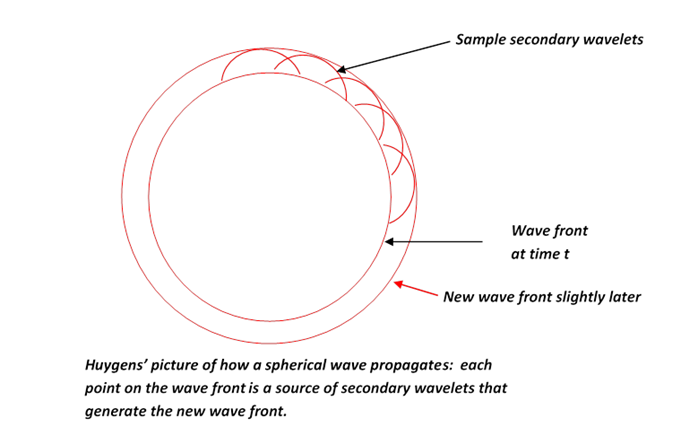
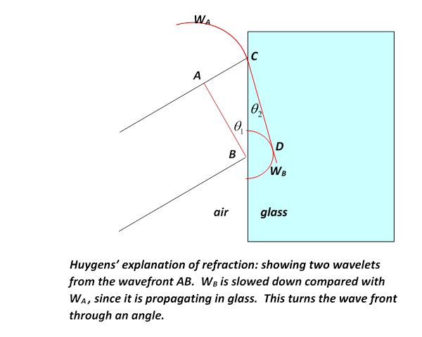
You might think that if a point on the wavefront is a new source, wouldn't the disturbance it generates be as likely to go backwards as forwards? Huygens did not address this point. In fact, it's not easy to give a short satisfactory answer. We'll discuss propagation of light (and of course other electromagnetic waves) fully in this lecture. Huygens' principle does explain why the wavefront stays spherical, and more important, it explains refraction—the change in direction of a wavefront on entering a different medium, such as a ray of light going from air into glass. Here's how: If the light moves more slowly in the glass, velocity instead of , with , then Huygens' picture predicts Snell’s Law, that the ratio of the sines of the angles to the normal of incident and transmitted beams is constant, and in fact is the ratio . This is evident from the diagram below: in the time the wavelet centered at A has propagated to C, that from B has reached D, the ratio of lengths AC/BD being . But the angles in Snell’s Law are in fact the angles ABC, BCD, and those right-angled triangles have a common hypotenuse BC, from which the Law follows.
Notice, though, the crucial fact: we get Snell's law on the assumption that the speed of light is slower in glass than in air. If light was a stream of particles, the picture would have to be that they encountered a potential change on going into the glass, like a ball rolling on a horizontal floor encountering a step, smoothed out a bit, to a different level. This would give a force perpendicular to the interface on going from one level to the other, and if the path is bent towards the normal, as is observed, the ball must speed up—so this predicts light moves faster in glass. It wasn't until the nineteenth century, though, that measuring the speed of light in glass (actually I think water) was technologically possible.
In fact, even in the early nineteenth century, the wave nature of light was widely doubted. Fresnel greatly improved Huygens' crude picture, fully taking into account the interference between secondary wavelets having different phases. One of the principal skeptics of the wave theory, the mathematician Poisson, pointed out that it was obvious nonsense because, using Fresnel's own arguments, it predicted that in the very center of the dark shadow of a sphere illuminated by a point source of light, there should be a bright spot: all the "light waves" grazing the edge of the sphere would generate secondary wavelets which would land at that spot in phase. A bright spot at the center of the dark disk seemed obvious nonsense, but an experimentalist colleague in Paris, Arago, decided to try the experiment anyway--and the spot was there. It's now called the Poisson spot, and it gave a big boost to the wave theory in France (it was already fully accepted in England, where Thomas Young did the double slit interference pattern, and compared it to the wave pattern in a similarly configured ripple tank, presenting the results to the Royal Society in 1803).
What is Diffraction?
Generally, the term is used to describe the slight deviations from classical ray optics: for example, with a point source of light, the shadow of an edge will be observed not to be simply a line between black and white, but to have narrow bands parallel to it, very close. Similarly the shadow of a small object: in this case diffraction and scattering refer to the same wave phenomenon. In introductory physics classes, it is often introduced as the pattern from monochromatic light shining through two parallel close slits on to a screen, creating a familiar pattern of successive light and dark bands where the two light sources are in and out of phase. This pattern is greatly clarified by going to a whole array of uniformly spaced slits, called a diffraction grating.
This can all be well explained by adding to Huygens' picture of secondary wavelets the fact that waves have a phase, and can therefore waves from different sources can add constructively or destructively, and the gradation between.
But to do this really properly, we can't get away with treating the slit as point (or line) sources, they have finite width, and, strictly, each point on the wave front generates wavelets, so even a single narrow slit will have some kind of diffraction pattern. From 1818 into the 1820's, Fresnel successfully analyzed diffraction. He was the first to realize that light is a transverse wave, and he analyzed the separation of polarizations by an anisotropic crystal. He also constructed diffraction patterns by adding waves, effectively integrating over continuous sources with appropriate phase factors.
However, this work was all done before it was realized that light is an electromagnetic wave. Obviously, a full analysis requires using Maxwell's equations to discover just how the fields (electric and magnetic) propagate from the source, holes or slits in a thin plate, to the screen, where the diffraction pattern appears.
Two centuries after Huygens, Kirchhoff was the first to attempt putting his picture on a firm basis. To illustrate his approach, consider the following standard diffraction scenario:
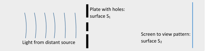
Light (or some electromagnetic wave, we'll call it light) is coming in from the left, it's got more or less flat wave fronts by the time it reaches the thin plate of perfectly conducting metal S1, which has various holes in it. We're only interested in the fields in the region from S1 to S2, and in particular the pattern of light on the perfectly absorbing plate S2.
Scalar Diffraction Theory
We begin with a baby version of the problem, called scalar diffraction theory, in which we consider not the two vector fields but a single scalar field ( could be a component of or ). Assume
and as usual take monochromatic fields, having time dependence , so
Kirchhoff's idea is that we know at S1; it's just that part of the incoming wave that hits the holes (this is a very thin screen) so between S1 and S2 it must be just the development of that wave, following the wave equation above. The tricky part is expressing this in precise mathematical terms. In fact, we've encountered a very similar problem in electrostatics, finding the field when we knew its value on the boundaries, such as the field from a given set of conductors set at given potentials. The solution there was discovered by George Green, and we'll be using Green's functions here too, so here's a very brief review.
We're trying to find a function satisfying in a volume given that we know its value on the boundary surface(s) (For our present diffraction problem, we're assuming we know its value as it comes through the screen, but far away in other directions we'll argue that it is sufficiently small we can neglect it.) Anyway, we introduce a second function, Green's function, that satisfies
Recall now Green's theorem for a pair of well-behaved scalar fields:
Taking the two functions as our satisfying the (Kirchhoff) equation above, and the volume integral on the left in the equation above can be written:
so, if we can do the surface integral, Green's work gives us the value of the function anywhere in the volume.
We need to evaluate (following Jackson's convention of having the normal pointing into the volume)
The standard Green's function for the Kirchhoff problem (meaning ignoring finite boundaries) is
giving
We argue at this point that the field can only really depend on its value at its source, the holes in the screen. After all, the other boundaries can be taken so far away that the wave hasn't reached them yet!
Of course, the part of the screen that isn't holes is close by, so we have to come up with some boundary condition there.
So Kirchhoff assumed:
1. At the apertures (openings in the screen S1) are just given by an incoming wave,
2. on the rest of S1,
Physically, this sounds reasonablebut unfortunately it's not mathematically rigorous: just as for the Laplace equation, if a function satisfies assumption 2 over a finite stretch of the boundary it's identically zero everywhere, unlike our proposed solution!
To try to improve, at least to get rid of the mathematical inconsistency, we'll take another look at Green's equation
As we discussed previously (in electrostatics), in practice we can't in practice specify and everywhere on the boundary before we've solved the problem, but it's often possible to specify one of them. The key to doing just that is to realize that the Green's function we're using, isn't the only possibility—we can always add any solution of That means we can find a Green's function that is itself identically zero on the boundary, or its normal derivative is. If we can do that (it's mathematically always possible, but may be technically difficult) then one of the terms in the above integral disappears, and we only need to specify or on the boundary. These are known as Dirichlet and von Neumann Green's functions (and boundary conditions) respectively.
That is, the Dirichlet Green's function satisfies
Then
Using the Dirichlet Green's function, it is mathematically consistent to take the boundary condition on S1 except at the openings. (We could alternatively work with von Neumann Green's functions.)
There is one case in which the Dirichlet and von Neumann Green's functions are easy to find: if the screen S1 is an infinite flat plane. In that case, the special Green's functions are derived from the "free" Green's function by adding another "free" Green's function at the image point (compare electrostatics) to get:
Here as usual, and where is the mirror image point of in the plane.
Thus if that is, in the plane.
Taking this Dirichlet function zeroes out one term in the integral for leaving
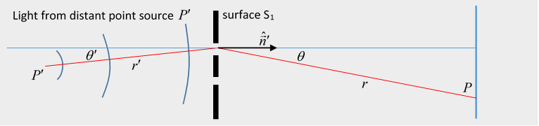
Not surprisingly, this formula is not the same as that using Kirchhoff's approximation. Just how different are they? Which one should we believe? (If either!) To investigate, we take a point source of "light" and find at a point both points being far from the screen.
We now assume that at S1 , in the openings and zero elsewhere.
It's clear that the Dirichlet formula above includes a term from whereas the original Kirchhoff approximation
gives the identical integral except with in place of (Neumann Green 's functions give ) (Remember the at the screen is the outgoing spherical waveform from the source, so the gives the ingoing )
In fact, all are based on an oversimplified analysis, but--it doesn't matter too much! Far and away the most important part of the integral is the rapidly oscillating phase, in all of them, and actually just a Huygens plus phase analysis. For most diffraction experiments, the angles are very small anyway, and the patterns are pretty accurately reproduced by these formulas.
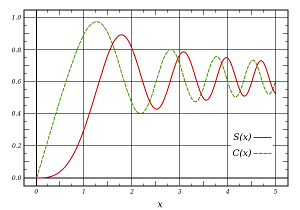
Fresnel Integrals
As an example, we work through Jackson Problem 10.11:
A perfectly conducting flat screen occupies half of the plane (say ) A plane wave of intensity and wave number is incident along the axis from Discuss the values of the diffracted fields in the plane parallel to the plane defined by Let the coordinates of the observation point be
Show that for the usual Kirchhoff approximation and in the limit and the diffracted field is
where
*** The generalized Kirchhoff approximation is
Since we can take , with some phase, can drop the term.
The variation of in the denominator is slowonly the phase matters.
Now at point we have so
To do the integral, we take the in the denominator to be constant, so take it out of the integral. Putting the above approximation into the phase term, and writing
, etc.
The integral is the same except that the lower limit is at so it is with
This is a Fresnel integral: