46. Plane Electromagnetic Waves
(Parts of Jackson 7.1 - 4)
Maxwell’s Equations for a Plane Wave in a Non-Conducting Dielectric
We've previously gone from the fields themselves to the potentials, and found wave equations for the potentials. This time, we're going to stick with the fields: it turns out to be more convenient for boundary conditions between different media, and is also helpful in building an intuitive understanding of various wave phenomena, as will become evident.
Here are Maxwell's equations for a single frequency wave (fields proportional to real part of an expression having time factor ) in a medium of constant permeability and susceptibility (both of which we initially take to be real), and with no (free) charges or currents present:
(That last equation is just )
These equations immediately lead to the Helmholtz wave equation:
with plane wave solutions of wave number
where
and the index of refraction
If this index, and therefore the wave velocity, is independent of frequency, we can add plane waves to get solutions of arbitrary shape propagating with constant profile in one dimension. However, in general the speed in a medium is frequency dependent, as evidenced by a prism.
So we'll stay for now with a single frequency,
The accompanying magnetic field is determined by Maxwell’s equations, which for this plane wave are:
meaning are all mutually perpendicular.
We put a unit vector here to emphasize that have the same size in the plane wave.
Notation: We Will Use rather than for Wave Phenomena
This is standard usage: the equations are less cumbersome, and in this next part of the course there is much overlap with engineering, where is standard.
The Wave Impedance
From the appropriate Maxwell equation above, assuming isotropy so
where is termed the wave impedance (or just impedance). Why is this an appropriate name? For a discussion of impedance in various systems, see the previous lecture. In the present case, it measures the resistance to the power flow (measured by the Poynting vector ) for a given strength wave source, (compare ) Since the dimensions of are amps/meter (think field from current in a long straight wire), and the electric field has units volts/meter, the impedance has units volts/amps, or, from Ohm’s Law, ohms.
In vacuum,
Fields and Energy in the Plane Wave
The two field amplitudes in the plane wave under discussion are
and
We established earlier that the energy flow per unit area is given by the real part of the complex Poynting vector, so
The time averaged energy density is
(Note: we use here where Jackson uses (for the wave direction), because in the very next section is the normal to the media interface, not the wave direction.)
And, putting the two equations above together, the energy is flowing at a speed
Taking frequency independent for now, this is both phase and group velocity. (We’ll deal with the frequency-dependent case later.)
To get some idea of the field magnitudes involved, consider the sunlight reaching the earth. The incident radiation intensity just above the atmosphere is about 1.4kW/sq meter, so the energy density is 1.4kJ in cubic meters. That is, and so More directly, since the Poynting flow we have
Now the engineer’s magnetic field is given by The physical field in the sunlight is and so a lot weaker than the Earth’s magnetic field. (If this looks like the magnetic field is a lot feebler than the electric fieldit isn’t. They both carry the same energy in the wave. We’re using SI units, handy in working with currents in wires and the corresponding electric and magnetic fields, perhaps not so natural for light waves. In the cgs system, the electric field is in statvolts (300V)/cm, and the magnetic field in gauss, and in a light wave the energy densities are numerically equal.)
Note: we’ll skip the end of Jackson 7.1, on complex normal vectors.
Polarization
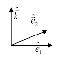
We choose two orthonormal vectors in the plane perpendicular to and write two possible solutions of the equations (assuming as usual that the physical field is the real part),
In both of these cases, the electric field vector only points along one direction. This is called a “linearly polarized” wave. The general solution at this frequency is
a combination of the two linearly polarized waves.
Now are in general complex numbers. If they have the same phase, the wave is linearly polarized in a plane at an angle to the axis. An important case is when they are out of phase by a quarter period, so
Remembering that the physical electric field is the real part, it's easy to see that its components along the vectors are out of phase by and this is precisely what happens when the tip of the electric field vector is describing a circle in the complex plane. Here (with the factor) it means the real electric field vector is also rotating, in a plane perpendicular to
Exercise: Check this out by writing down the real components of the electric field along the axes.
The field could be rotating either way: for left circularly polarized light the rotation looks counterclockwise as it approaches you, this is also called positive helicityas we’ll discuss later, the angular momentum of the fields points in the direction of propagation. (This of course relates to photon angular momentum, but we won’t pursue that here.)
Note: Stokes Parameters, Jackson 7.2. In 1852 Stokes wrote down a set of four parameters, each being quadratic in the electric field strength (and measurable), to give a full description of a monochromatic beam: its total intensity, the relative intensities of polarization states, and phase differences between those states. These parameters are fully described in Born and Wolf and Wikipedia, and we won’t cover them here.
Reflection and Refraction at a Plane Interface
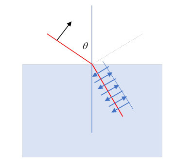
The plane of incidence is the plane containing the incoming wave number vector and the normal to the surface,
The incoming wave has frequency and fields
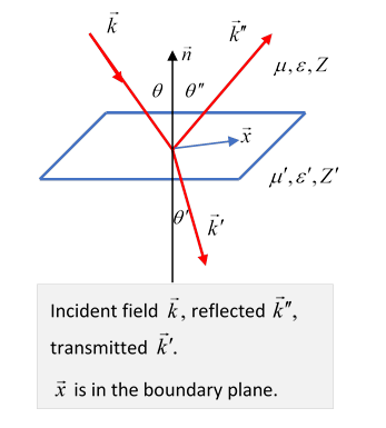
We will label the familiar refracted and reflected waves (see diagram) as:
We’ll now find these in terms of the ingoing field, using the boundary conditions.
First, the tangential components of must be continuous at the boundary. Obviously, the frequencies are all the same, and for anywhere in the boundary plane we must have
to ensure that the wave phase pattern in the boundary plane matches for all three waves at all times. It follows that can only differ from by some multiple of so they lie in the plane of incidence.
Since (both being in the same medium, and same ) it follows from the equality of components in the boundary -plane that the angle of incidence (the angle between the incoming ray and the normal to the plane) must equal the angle of reflection, and since the ratio is the ratio of the velocities in the two media (same ), and Snell's law follows,
Kinetic vs Dynamic Properties
In the previous lecture, we looked at the one-dimensional system of waves on a taut string: there were two basic physical variables, the string density and the tension
But the variables directly relevant in analyzing phenomena were the combinations: wave speed and (for crossing a boundary between media) impedance
For light waves in an isotropic medium, the relevant basic variables are the electric permittivity and the magnetic permeability
But, just as for the string, the variables we need to analyze motion are the combinations: wave speed and impedance
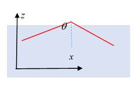
Consider now the situation diagrammed below of a light ray in vacuum encountering a smooth glass surface, so there is some reflection and some transmission, as shown.
Kinetic Properties: The directions of the reflected and refracted rays give the geometry of the motion, hence the name kinetic properties. All we need to find them are the velocities in the two media, plus the knowledge that they are plane waves (to match phases on the boundary surface). Note: Snell’s Law is written in terms of the index of refraction, thus the wave velocity,
Dynamic Properties: these include the actual power reflected and refracted, and phase change on reflection. Here the impedance plays a central role. (It played no role in Snell’s Law.)
Note, however, that many media have magnetic permeability close to unity, in which case and for those media does not appear in the equations, such as Jackson (7.42).
Calculating Power Transmitted/Reflected from Boundary Conditions
The relative wave amplitudes can be calculated from the continuity of:
(a) the normal to the surface components of (since and in the absence of free surface charge ),
(b) the tangential to the surface components of (no surface current).
Following Jackson, we'll write it all in terms of fields, and use for discontinuity. Using
It turns out, though, that for the wave fields we are dealing with, the second pair of equations is all we need to solve the problem.
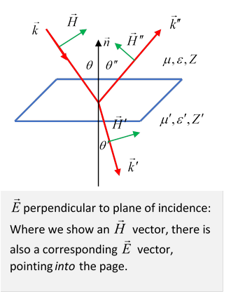
Case I: Ingoing electric field perpendicular to plane of incidence
(Reminder: Plane of incidence is plane defined by vectors it also contains )
For at right angles to the plane of incidence, it's tangential to the reflecting surface, and the third condition above gives
(Remember is perpendicular to etc.)
Note: we have gone from a vector equation to what looks like an “amplitude” equation, but it’s really a component equation: as we are about to show, if is very large, so the wave is almost all reflected, and is negative, this is the familiar phase reversal on reflection from a higher impedance medium.
From the fourth Jackson boundary condition gives (using and )
Exercise: Check this result.
Writing the two equations
we find the reflection and transmission amplitudes for ingoing electric field perpendicular to plane of incidence
Zangwill’s (17.36). (He refers to waves with the electric field in the plane of incidence as p-waves, electric field perpendicular to plane of incidence as s-waves, because the German word for perpendicular begins with s.)
Of course, if you want this only in terms of the incident angle you must use Snell’s law to eliminate as Jackson does.
If the materials are magnetically equivalent to the vacuum, then and
then using , we find the simple formula, originally derived by Fresnel,
and the reflection coefficient (defined as reflected power fraction) is the square of this.
Case II: Ingoing electric field in the plane of incidence
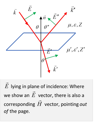
For the electric field vector in the plane of incidence, tangential component continuity for gives
and rearranging slightly,
from which the reflection and transmission fields for ingoing electric field in the plane of incidence are
If we assume the materials are magnetically equivalent to the vacuum, (which is often the case) then and inserting Snell’s law, we get the simple expression due to Fresnel
Exercise: check this formula, and interpret what happens when
Normal Incidence
For the reflected and transmitted fields respectively
What can we learn from these formulas?
Start with normal incidence: Note that for the reflected ray goes to zerohardly surprising, that means that optically the media are indistinguishable. More interesting, for the reflected ray has the opposite sign: there is a phase change of on reflection from a more-dense medium, no phase change on reflection from a less dense one, and never a phase change on refraction. This is true of all wave phenomena: for example, a wave on a string that has a discontinuous change in linear densitycheck out our animation!
Brewster's Angle
Notice now that for the electric field polarized in the plane of incidence, the reflection goes to zero if (taking )
Could this happen? Yes: if (Check it!) Since this means the reflected ray and the refracted ray are at right angles. The physical origin of the reflected ray is that the refracted ray causes dipole oscillations in the material, these radiate. But an oscillating dipole, as we shall learn, emits zero radiation along its axis. (Obviously, this non-reflection won’t happen if the ingoing electric field is perpendicular to the plane of incidence.)
This angle is called Brewster's angle. For unpolarized incident radiation, at this angle only waves polarized with the electric field perpendicular to the plane of incidence are reflected, so polarized light results. Even close to this angle, the light is predominately polarized. This is why polaroid sunglasses cut glare, which is reflected light.
Total Internal Reflection: the Goos-Hanchen Effect
From Snell's law, so for light going into a less dense medium, such as out of glass or water into air, if is gradually increased from zero until the angle will increase from zero to the light emerging from the water will come out parallel to the surface, and for further increase in no light will come out: it will all be reflected. However, the fields still have to obey the boundary conditions, so there has to be some nonzero field on the boundary, even in the "forbidden" zone. We can satisfy the boundary condition for
as follows: define
recalling then the wave vector in the second (less dense) medium can be written
As previously argued, the -component of must match that of the incoming wave, so this result follows (check it!).
Therefore the waveform in the "forbidden" region decays exponentially on going away from the interface:
sometimes called evanescent waves.
This is classical physics, but it's classical wave mechanics. The mathematics is identical to the familiar quantum one-dimensional problem of an electron encountering a step barrier higher than its kinetic energy. There is total reflection, but the wave function penetrates the barrier (and decays exponentially in the "forbidden" region), otherwise the boundary conditions on the wave function (continuity and continuity of derivative for a finite barrier) cannot be met. Note that the wave is still moving in the -direction even as it decays in the -direction, so if a narrow beam is reflected, it will come out as if reflected from a distance below the surface of order the decay length (OK, a naïve explanation, see further discussion below). This is called the Goos-Hanchen effect, first predicted by Isaac Newton.
Following Jackson, the Poynting flow normal to the surface is
and soBut is pure imaginary, so the normal direction Poynting flow in the less optically dense medium is zero in contrast to the incoming and reflected terms, all being evaluated with the same fields right at the surface.
The reality of the corresponding exponentially decaying light wave outside the glass can be confirmed by bringing a parallel sheet of glass very close to the surface: just as for a quantum barrier of finite width, some light will get through.
Here’ another way to think about the Goos-Hanchen effect. When the reflected beam of course has amplitude equal to the incoming beam, but (in contrast to the regime) there is a varying phase shift, .
This is from Jackson problem 7.7, where it is also pointed out that to have a finite width incoming beam (so you can see the sideways shift) it is necessary to have ingoing waves over a (narrow) range of wavenumbers, which will be phase shifted by differing amounts, and give rise to the effect. But actually we can make it plausible by taking just two nearby (in the same way two close frequencies generate a string of “wave packets”).
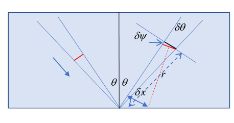
Consider two ingoing rays, same wavelength, same phase, but differing in ingoing angle by a very small After reflection, they will be slightly out of phase, by so a lag distance given by
Looking at the diagram, we see that this small phase difference slightly rotates the “wave front” by which we mean the line of wave crests, shown in red, by a small angle The black line is where the wave front would be without this phase shift. From the small narrow triangle,
This wave front corresponds to an outgoing wave from a point displaced to the right: see the diagram, the red dotted line is perpendicular to the wave front, and apparently originates from a point displaced by
in the direction perpendicular to the outgoing ray. This is the result given in Jackson problem 7.7, and assuming varies little over a (small) range of ingoing angles, we can integrate over a range and form a proper wave packet. The result as stated is good for both polarizations, but the phase shifts are not the same.
To take the perpendicular to plane of incidence case, put and use to write Jackson 7.39 in our notation
We see that is in a right-angled triangle with sides and therefore hypotenuse That is,
and differentiating
so and
Jackson’s 7.48.